Construction and Working:
The series motor starter serves the same purpose as the three and four-point starters employed with shunt and compound wound motors. However, the series motor starter has different internal and external connections.
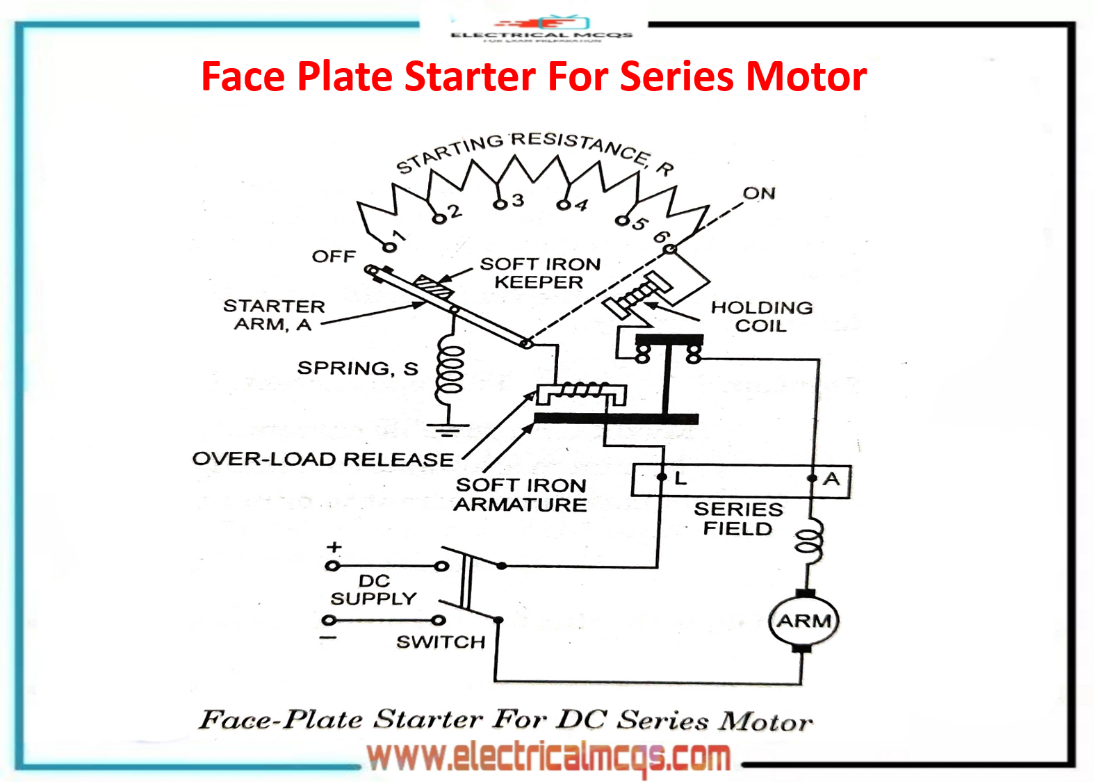
A series motor starter with holding coil and over-load release is illustrated in fig.
Holding coil protects the motor against "no-volt" and "no-load" whereas over-load release protects the motor against the flow of excessive current.
The dc supply is switched on and the starter arm is moved to the right for starting the motor. As soon as the starter arm comes in contact with stud No. 1, the series motor gets connected, through the total starting resistance, to the supply mains and when the starter arm reaches the "ON" position the starting resistance is completely cut off and the motor starts running at normal supply.
The arm is held in the “ON” position by the holding coil. Should the supply fails while the motor is running, or the motor current falls to too low a value (and consequently the speed becomes excessive), the pull of the holding the coil is reduced to an extent that it can no longer hold the arm against the spring action attached to it and the starter arm flies back to the OFF position and thus the motor gets disconnected automatically from the supply mains.
The over-load release is connected in series with the motor, so carries the total motor current. When the input current to the motor becomes excessive, which also flows through the over-load release coil, the soft iron armature gets lifted to break the holding coil circuit.
Thus the holding coil gets demagnetised and the starter arm returns back to the OFF position under the action of the spring attached to it and the motor gets disconnected automatically from the supply mains.
For switching off the dc series motor, the line switch should always be opened rather than throwing back the starting arm, as in the case of dc shunt and compound motors.
If it is done, then heavy sparking is caused at stud 1, because here the field circuit is broken and the entire energy stored in the magnetic field is dissipated in the form of a heavy spark.
However, there is one significant difference. In the case of a de series motor, the flux does not remain constant but varies with the current because the line current, field current, and armature current are the same.
Thus the back emf at any given speed varies as the current varies between the upper and lower limits.
The practical result of this is that a series motor starter has a smaller number of steps than that required for a starter of a dc shunt motor of the same rating with the same current limits.
This is because an increase in current causes an increase in back emf and thus the current rise tends to be self-limiting.
As a result of the fewer steps, the resistance of each section of the starter resistor is greater than for the shunt motor starter.
Since flux varies during the starting operation and its relation to the field current is non-linear, the determination of the number of steps is rather complicated.
It will be found that the differences between the values of the resistances of the various sections are proportionately less than those for the shunt motor starter, although the number of sections is smaller.
In practice, the values are not critical in the series motor starter and it may be possible to use identical values for all the sections. This is due to the self-regulating effect, mentioned above.


