
1. HVDC Homo polar links uses
A. One conductor usually of negative polarityB. One conductor usually of positive polarity
C. Two conductors of positive and negative polarity
D. Two conductors of negative polarity
Answer: D. Two conductors of negative polarity
Explanation:
Monopolar link:
- It has a single conductor of negative polarity and uses earth or sea for the return path of current.
- Sometimes the metallic return is also used.
- In the Monopolar link, two converters are placed at the end of each pole.
Bipolar link:
- The Bipolar link has two conductors one is positive, and the other one is negative to the earth.
- The link has a converter station at each end.
- The midpoints of the converter stations are earthed through electrodes.
- The voltage of the earthed electrodes is just half the voltage of the conductor used for transmission of the HVDC.
- It has two independent circuits and can be operated as a monopolar link in an emergency
Homopolar link:
- It has two conductors of the same polarity usually negative polarity, and always operates with earth or metallic return.
- In the homopolar link, poles are operated in parallel, which reduces the insulation cost.
2. Identify a valid disadvantage of HVDC transmission lines.
A. High radio interferenceB. Expensive converters
C. High corona loss
D. Skin effect
Answer: B. Expensive converters
Explanation:
- High voltage direct current (HVDC) power systems use D.C. for transmission of bulk power over long distances.
- For long-distance power transmission, HVDC lines are less expensive, and losses are less as compared to AC transmission.
- It interconnects the networks that have different frequencies and characteristics.
- HVDC transmission is economical only for long-distance transmission lines having a length of more than 600kms and for underground cables of length more than 50kms.
- DC lines are cheaper than the AC lines, but the cost of DC terminal equipment is very high as compared to AC terminal cables as shown in the figure below. Thus, the initial cost is high in the HVDC transmission system, and it is low in the AC system.
- The point where two curves meet is called the breakeven distance. Above the breakeven distance, the HVDC system becomes cheaper. Breakeven distance changes from 500 to 900 km in overhead transmission lines.
Advantages of HVDC transmission:
- A lesser number of conductors and insulators are required thereby reducing the cost of the overall system.
- It requires less phase to phase and ground to ground clearance.
- Their towers are less costly and cheaper.
- Corona loss is less as compared to HVAC transmission lines of similar power.
- Power loss is reduced with DC because fewer numbers of lines are required for power transmission.
- HVDC system uses earth return. If any fault occurs in one pole, the other pole with ‘earth returns’ behaves like an independent circuit. This results in a more flexible system.
- HVDC acts as the asynchronous connection between two AC stations connected through an HVDC link, i.e. it interconnects two substations with different frequencies.
- Due to the absence of frequency in the HVDC line, losses like skin effect and proximity effect does not occur in the system.
- It does not generate or absorb any reactive power. So, there is no need for reactive power compensation.
- Very accurate and lossless power flows through the DC link.
Disadvantages of HVDC transmission:
- Converter substations are required at both the sending and the receiving end of the transmission lines, which result in increasing the cost.
- Inverter and rectifier terminals generate harmonics which is reduced using active filters which are also very expensive.
- The inverter used in Converter substations has limited overload capacity.
- Circuit breakers are used in HVDC for circuit breaking, which is also very expensive.
- It does not have transformers for changing the voltage levels.
Conclusion:
- Considering all the advantages of DC, it seems that HVDC lines are more proficient than AC lines. But, the initial cost of the HVDC substation is very high and their substation equipment is quite complicated.
- Thus, for long-distance transmission, it is preferable that power is generated in AC, and for transmission, it is converted into DC and then again converted back into AC for final use.
- This system is economical and also improves the efficiency of the system.
HVDC Transmission System
- Low losses.
- Better Voltage Regulation and Control ability.
- Transmit more power over a longer distance.
- Less insulation is needed.
- Reliability is high.
- Asynchronous interconnection is possible.
- Reduced line cost due to fewer conductors.
- Towers are cheaper, simple, and narrow.
HVAC Transmission System
- Losses are high due to the skin effect and corona discharge
- Voltage regulation and Control ability are less.
- Transmit less power compared to an HVDC system.
- More insulation is required.
- Low Reliability.
- Asynchronous interconnection is not possible.
- The line cost is high.
- Towers are bigger compared to HVDC.
3. A bipolar DC line has _________ conductor(s).
A. threeB. one
C. four
D. two
Answer: D. two
Explanation:
Types of HVDC Links:
Three types of HVDC Links are considered in HVDC applications which are
Monopolar Link:
- A monopolar link as shown in the above figure has one conductor and uses either ground and/or sea return.
- In applications with DC cables (i.e., HVDC Light), a cable return is used.
- Since the corona effects in a DC line are substantially less with negative polarity of the conductor as compared to the positive polarity, a monopolar link is normally operated with negative polarity.
- Bipolar DC link as shown in the above figure has two conductors, one positive and the other negative.
- Each terminal has two sets of converters of equal rating, in series on the DC side.
- The junction between the two sets of converters is grounded at one or both ends by the use of a short electrode line.
- In this type of link as shown in the above figure two conductors having the same polarity (usually negative) can be operated with ground or metallic return.
- Due to the undesirability of operating a DC link with ground return, bipolar links are mostly used.
- A homopolar link has the advantage of reduced insulation costs, but the disadvantages of earth return outweigh the advantages.
4. Which of the following will be provided to reduce the harmonics on the ac side of an HVDC transmission line?
A. Synchronous motors in over excited conditionB. Shunt capacitor
C. Static compensator
D. Shunt filters
Answer: D. Shunt filters
Explanation:
Reactive VAR Requirement of HVDC Converters:
- Converters at both ends of the HVDC line draw reactive power from the ac system.
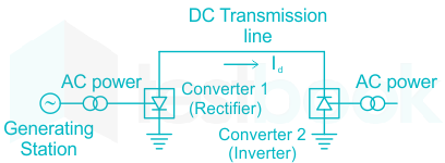
- Filters are provided on the AC side of the converter of the HVDC transmission line, to reduce the harmonic current and voltage of the AC side.
- If filters are not provided on the AC side of the HVDC transmission line, it would produce interference with other equipment or with communication lines.
The below figure shows a typical AC-DC system.
Therefore, a shunt filter is designed such that it presents a low impedance to all the a.c. harmonic currents and capacitive impedance to the fundamental frequency.
5. Which of the following statement is TRUE in case of a HVDC system?
A. neither charging current nor skin effectB. charging current as well as skin effect
C. charging current but no skin effect
D. no charging current but skin effect
Answer: A. neither charging current nor skin effect
Explanation:
- Both skin effect and charging current are absent in the HVDC system.
- Due to DC supply, the current distribution is the same on the wire so there is no skin effect and shunt capacitance offers infinite impedance to DC voltage so no charging current.
Advantages of HVDC transmission:
No Skin Effect:
- In HVDC transmission current distributes uniformly over the cross-section of the conductor. Hence no loss due to skin effect is encountered.
- For the same current-carrying capacity HVDC lines have lesser cross-section compared to HVAC lines
Lower Transmission Losses:
- HVDC transmission requires only two conductors.
- Therefore the power loss in the DC line will be lesser compared to the AC line
Good voltage Regulation:
- In DC lines, a voltage drop does not exist due to inductive reactance. Voltage Regulation will be better in HVDC transmission
Surge Impedance Loading:
- Long EHV lines are loaded to less than 80% of the natural load. No such condition is applicable in HVDC transmission
- No Line Loading Limit: The permissible loading limit on EHV AC lines is limited by the transient stability limit and the line reactance to almost one-third of the thermal rating of the conductors. No such limitations exist in the case of HVDC line
- Lesser Corona Loss and Radio Interference: Corona Loss directly proportional to frequency. Therefore in the DC line, corona loss will be lesser compared to the AC line.
Higher Operating Voltages:
- The design of Insulation of the conductors for high voltage transmission lines depends on the switching surges but not on lightning surges (for voltages beyond 400kV switching surges are more severe than lightning surges).
- The level of switching surge will be lesser in the DC line compared to the AC line. Hence less insulation is required in DC line
Reactive Power Compensation:
- Unlike the AC line DC line does not require any reactive power compensation devices. This is because of the absence of charging currents and power factor operation.
- Short circuit currents during a fault in DC line will be lesser compared to AC lines.
- Absence of the charging currents and limitations on the cable lengths.
- Economical and greater reliability.
6. Consider the following advantages with respect of HVDC transmission:
1. Long distance transmission2. Low cost of transmission
3. Higher efficiency Which of the above advantages are correct?
Options:
A. 1 and 2 only
B. 1 and 3 only
C. 2 and 3 only
D. 1, 2 and 3
Answer: D. 1, 2 and 3
Explanation:
High voltage direct current (HVDC) power systems use D.C. for transmission of bulk power over long distances. For long-distance power transmission, HVDC lines are less expensive, and losses are less i.e. more efficient as compared to AC transmission.
Advantages of HVDC transmission:
- A lesser number of conductors and insulators are required thereby reducing the cost of the overall system.
- It requires less phase to phase and ground to ground clearance.
- Their towers are less costly and cheaper.
- Corona loss is less as compared to HVAC transmission lines of similar power.
- Power loss is reduced with DC because fewer numbers of lines are required for power transmission.
- HVDC system uses earth return. If any fault occurs in one pole, the other pole with ‘earth returns’ behaves like an independent circuit. This results in a more flexible system.
- HVDC acts as the asynchronous connection between two AC stations connected through an HVDC link, i.e. it interconnects two substations with different frequencies.
- Due to the absence of frequency in the HVDC line, losses like skin effect and proximity effect does not occur in the system.
- It does not generate or absorb any reactive power. So, there is no need for reactive power compensation.
- Very accurate and lossless power flows through the DC link.
Disadvantages of HVDC transmission:
- Converter substations are required at both the sending and the receiving end of the transmission lines, which result in increasing the cost.
- Inverter and rectifier terminals generate harmonics which is reduced using active filters which are also very expensive.
- The inverter used in Converter substations has limited overload capacity.
- Circuit breakers are used in HVDC for circuit breaking, which is also very expensive.
- It does not have transformers for changing the voltage levels.
7. A DC reactor is connected in series with each pole of a converter station in order to
A. prevent commutation failures in the inverterB. supply reactive power to the converter
C. improve system stability
D. increase the power transfer capability
Answer: A. prevent commutation failures in the inverter
Explanation:
Commutation failures:
- Commutation failure is a common fault of inverters
- It is the result of the failure of the incoming valve, due to sufficient extension time, to take over the direct current before the commutating voltage reverses its polarity.
- Thereafter, the direct current is shifted back from the incoming valve to the outgoing valve.
- It is not due to a malfunction of the valve, but due to AC DC condition outside the bridge.
- It is due to high DC current, low AC voltage (due to AC short circuit), late ignition, or a combination of these.
- Nearly all inverter valve falts lead to results similar to commutation failures.
DC reactors:
- It limits di/dt rise to prevent commutation failure in the inverter of one bridge when the voltage across the other bridge collapses.
- It reduces the incidence of commutation failure in inverters during AC dip
- It reduces the harmonic voltage and current in the DC link
- It reduces current ripples
- It limits the crest of the short circuit current in the DC line.
8. Under normal conditions, an HVDC link operates with:
(CC – constant current; CEA – constant excitation angle; CIA – constant ignition angle)
A. CC control at rectifier station and CEA control at inverter station
B. CIA control at rectifier station and CC control at inverter station
C. both at CC control
D. both at minimum delay angle control
Answer: A. CC control at rectifier station and CEA control at inverter station
A. CC control at rectifier station and CEA control at inverter station
B. CIA control at rectifier station and CC control at inverter station
C. both at CC control
D. both at minimum delay angle control
Answer: A. CC control at rectifier station and CEA control at inverter station
Explanation:
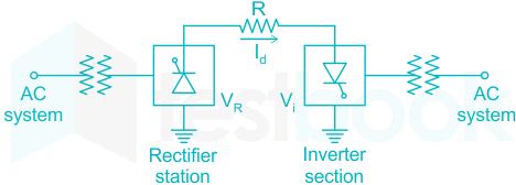
Control characteristics of HVDC link:
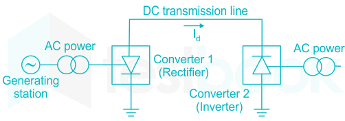
The major components of an HVDC transmission system are converter stations where conversions from AC to DC (Rectifier station) and from DC to AC (Inverter station) are performed.
A point to point transmission requires two converter stations. The role of rectifier and inverter stations can be reversed (resulting in power reversals) by suitable converter control.
Important points:
- The Natural Voltage (NV) Characteristic corresponds to zero delay angle α=0.
- The Constant Ignition Angle control is a similar characteristic that is parallel to the NV characteristic with a controllable intercept V0 cosα.
- The Inverter is usually operated at a constant extinction angle(CEA). This has the characteristic equation given by Vd=(V0cosδ - 3ωLC / Id).
- In a d.c. link it is common practice to operate the link at constant current rather than a constant voltage. Of course, constant current means that current is held nearly constant and not exactly constant.
- In constant current control, the power is varied by varying the voltage. There is an allowed range of current settings within which the current varies.
- The complete characteristic of each convertor has the N.V. characteristic and equipped with C.C. control and the C.E.A control.
- The constant current controller adjusts the firing angle (α)so that a current will be maintained even for short-circuits on the d.c. line.
- The C.C. control is present in the inverter too, although the inverter is not usually operated in that region.
- The rectifier is normally operated in the C.C. region while the inverter is operated in the C.E.A. region.
9. Which of the following scheme is used for coupling ac systems of different frequencies?
A. FACTS deviceB. cyclo converter
C. back to back dc link
D. none of the above
Answer: C. back to back dc link
Explanation:
Back to Back dc-link:
- A back-to-back connection is the direct connection of the output of one device to the input of a similar or related device.
- A back-to-back connection for electric power transmission is a high-voltage direct-current (HVDC) system with both ends in the same switchyard.
- This is used to couple asynchronously operated power grids or for connecting power grids of different frequencies where no DC transmission line is necessary.
- The back-to-back dc-link reduces the overall conversion cost, improves the reliability of the DC system.
10. The operation of a TCSC is prohibited for firing angles in the resonance region, since it offers to the network:
A. a low impedanceB. a high current
C. a low voltage
D. a high impedance
Answer: D. a high impedance
Explanation:
TCSC (Thyristor controlled series capacitor):
- A TCSC is a series-controlled capacitive reactance that can provide continuous control of power on the ac line over a wide range.
- TCSC consists of a series compensating capacitor (C) shunted by a thyristor controlled reactor (TCR).
- TCR is a variable inductive reactor (XL) tuned at firing angle α.
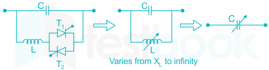
Figure: Equivalent circuit of TCSC
The variation of XL with respect to α can be given as αααXL(α)=XLππ−2α−sin2α
For the variation of α from 0 to 90, XL(α) varies from actual reactance (XL) to infinity.
This controlled reactor is connected across the series capacitor so that the variable capacitive reactance is possible across the TCSC which modifies the transmission line impedance.
Reactance characteristic curve:
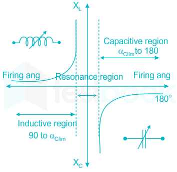
It is drawn between the effective reactance of TCSC and firing angle α.
The effective reactance XTCSC(α) of TCSC operates in three regions, inductive region, capacitive region, and resonance region.
The inductive region starts increasing from TCR reactance XL||XC value to infinity and decreasing from infinity to capacitive reactance XC for the capacitive region.
Between the two regions, resonance occurs (Parallel resonance) when XL(α) = XC. In this region due to parallel resonance, the parallel combination of TCR and capacitor will act as an open circuit and offers very high impedance to the network.
11. A static synchronous series compensator injects:
A. a current in quadrature with the system voltageB. a voltage in quadrature with the line current
C. a current in phase with the line current
D. a voltage in phase with the system voltage
Correct Answer: B. a voltage in quadrature with the line current
Explanation:
Static Synchronous series compensator:
- Static Synchronous Series Compensator (SSSC) is a modern power quality FACTS device that employs a voltage source converter connected in series to a transmission line through a transformer.
- The SSSC operates like a controllable series capacitor and series inductor.
- The SSSC injects a balanced set of voltage at the fundamental frequency that lags or leads behind the line current by 90° i.e in quadrature with the line current.
- This means that SSSC can be controlled to provide a series capacitive or inductive compensation.
- If the SSSC is provided with a storage source then it can exchange real power with the power system.
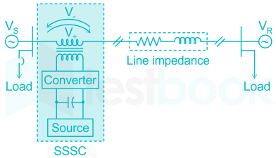
Figure: Static synchronous series compensator.
- The voltage-source converter is used to convert the DC input voltage to an AC output voltage.
- Transformer couples the SSSC to the transmission line.
- Energy Source provides voltage across the DC capacitor and compensation for device losses.
Applications:
- The SSSC is typically applied to correct the voltage during a fault in the power system.
- Power factor correction through continuous voltage injection and in combination with a properly structured controller.
- Reduces harmonic distortion by active filtering.
- Power flow control and Load balancing in interconnected distribution networks.
12. Transmission of bulk power between India and Sri Lanka is possible
A. using ac over-head transmission lineB. using ac submarine cable
C. using either ac or dc submarine cable
D. using dc submarine cable
Answer: D. using dc submarine cable
Explanation:
High voltage direct current (HVDC) power systems use D.C. for transmission of bulk power over long distances. For long-distance power transmission.
Indo-Srilanka HVDC Inter Connecter Link:
± 400 kV, 4 x 250 MW HVDC Bipole Transmission Link
From Madurai (India) to Sri Anuradhapura (Sri Lanka)
Project having Overhead line (approx. 334 km) and DC Submarine Cable (approx. 90 km)
Important Points:
Advantages of HVDC transmission:
- A lesser number of conductors and insulators are required thereby reducing the cost of the overall system.
- It requires less phase to phase and ground to ground clearance.
- Their towers are less costly and cheaper.
- Corona loss is less as compared to HVAC transmission lines of similar power.
- Power loss is reduced with DC because fewer numbers of lines are required for power transmission.
- HVDC system uses earth return. If any fault occurs in one pole, the other pole with ‘earth returns’ behaves like an independent circuit. This results in a more flexible system.
- HVDC acts as the asynchronous connection between two AC stations connected through an HVDC link, i.e. it interconnects two substations with different frequencies.
- Due to the absence of frequency in the HVDC line, losses like skin effect and proximity effect does not occur in the system.
- It does not generate or absorb any reactive power. So, there is no need for reactive power compensation.
- Very accurate and lossless power flows through the DC link.