

One of the ratio arms consists of resistance and capacitance in parallel. Hence it is simple to write the bridge equations in the admittance form.
The general bridge balance equation is,


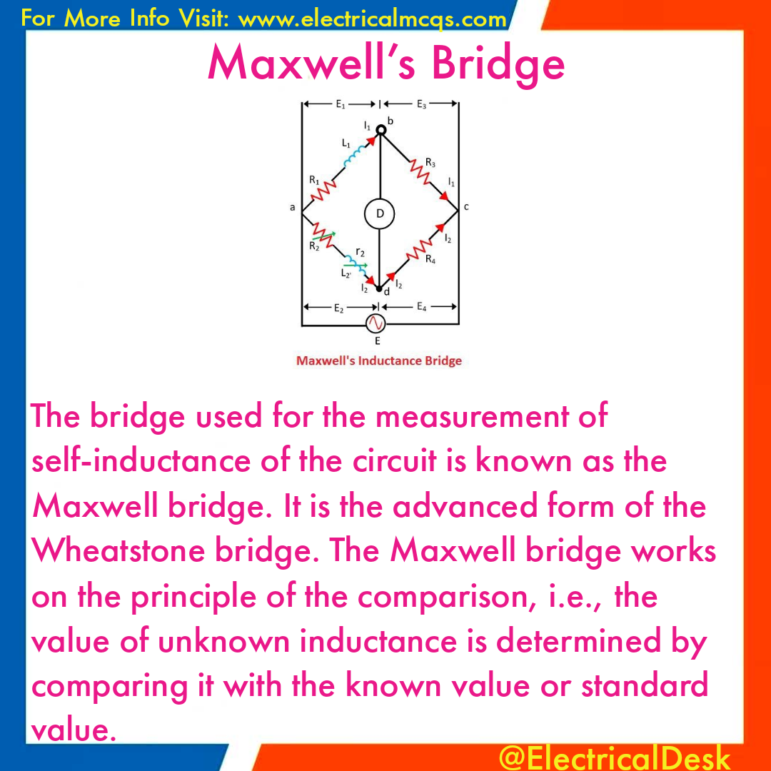
The resistances are expressed in ohms, the inductances in henries and capacitance in farads.

The advantages of using standard known capacitor for measurement are,
1) The capacitors are less expensive than stable and accurate standard inductors.
2) The capacitors are almost lossless.
3) External fields have less effect on a capacitor. The standard inductor requires well shielding in order to eliminate the effect of stray magnetic fields.
4) The standard inductor will not present its rated value of inductance unless the current flow through it is precisely adjusted.
5) The capacitors are smaller in size.
This bridge is also called Maxwell
Advantages of Maxwell Bridge
The advantages of the Maxwell bridge are,
1) The balance equation is independent of losses associated with inductance.
2) The balance equation is independent of the frequency of measurement.
3) The scale of the resistance can be calibrated to read the inductance directly.
4) The scale of R1can be calibrated to read the Q value directly.
5) When the bridge is balanced, the only component in series with coil under test is resistance R2. If R2 is selected such that it can carry a high current, then heavy current-carrying capacity coils can be tested using this bridge.
Disadvantages of Maxwell Bridge
The disadvantages of the Maxwell bridge are,
1) It cannot be used for the measurement of high values. Its use is limited to the measurement of low values from 1 to 10.
This can be proved from a phase angle balance condition which says that sum of the angles of one pair of opposite arms
must be equal.
Θ1 + Θ4 = Θ2 + Θ3
But Θ2 + Θ3 are zero, as the corresponding impedances are pure resistances.
For high Q values, the angle Θ4 is almost 90°. Hence 0, must be - 90°. But, gets decided by the parallel combination of R1 and C1.
To get Θ1 as almost 90° the value of R1 should be very very high.
Practically such high resistance is not possible. Hence high Q values can not be measured.
2) There is an interaction between the resistance and reactance balances. Getting the balance adjustment is a little difficult
3) It is unsuited for the coils with low Q values, less than one, because of the balance convergence problem.
4) The bridge balance equations are independent of frequency. But practically, the properties of the coil under test vary with a frequency which can cause an error.
Commercial Maxwell bridge measures the inductance from 1 - 1000 H, with +- 2 % error.