Shunt Capacitors :


The important reason of low voltage during maximum load conditions is the requirement of reactive current needed by induction motors.
Active power flows in lines from the generating station. But reactive power needed by consumer's equipment can be generally by installing static capacitors, thus reducing reactive power flow through the line.
This reduces voltage drop in the line and help in maintaining the voltage within given limits.
The static capacitors are of two types namely :
1. Shunt capacitors
2. Series capacitors.
These are named after the method of connection of the bank. Shunt capacitors are commonly used on 33 kV and 11 kV systems to improve the power factor and consequently the voltage of the system.
A shunt capacitor bank connected with an 11 kV bus in Fig.

Shunt capacitors draw almost a fixed amount of leading current which is superimposed on the load current.
This reduces the reactive component of the load current thus improving the power factor.
Reduced current and improved power factor reduces the voltage drop of the lines. Thus the resultant effect is voltage improvement.
A single line diagram showing 33 kV substation with 11 kV feeders With 11 kV capacitor bank is in Fig.

The capacitor banks are switched on during peak load conditions. At low load periods, capacitors are disconnected.
In addition to the above method of voltage regulation, another method is to install solid connected capacitors with each induction motor.
The capacitor is connected to the system when the motor is operated. It is a useful method as a maximum benefit from the reactive power-producing equipment is obtained by compensation at each individual load.

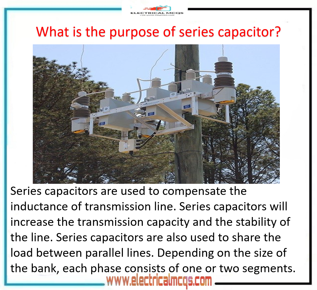
Series Capacitors:
Lamp Flicker:
There are two ways of voltage drop in the distribution system. One is a normal drop in voltage from no load to full load.
The other is a dip in the voltage due to sudden load on the system.
The impact of sudden load causes an abrupt change in the intensity of illumination of lamps called as lamp flickers.
Mostly lamp flicker's are caused by the starting of motor, use of electric welding sets and operation of arc furnaces, grinders and hammer mills, The human eye is quite sensitive and monitors even slight variations in light intensity.
Thus perceptible lamp flickers cause complaints from the consumers.
The voltage changes resulting in lamp flicker can be either cyclic or non-cyclic in nature. Generally, cyclic flicker is more objectionable.
The flicker in voltage may occur in primary distribution as well as a secondary distribution line.
Power supply utilities take necessary measures to reduce the lamp flicker.
There are two remedial measures adopted to solve the problem
1. System change,
2. Use of series capacitors.
System Change :
In secondary distribution circuits the following change reduces the voltage dip:
(a) Locate transformer near to the source of flicker.
(b) Increase the size of secondary distribution conductors and transformers.
(c) Adopt banking of transformers,
In primary circuits the following change reduces the voltage dip :
(a) Separate out the primary circuit which has source of flicker.
(b) Use higher size conductors on primary circuits,
Use of series capacitors :

Capacitors connected in series with primary distribution lines compensate the inductive reactance voltage drop thus reduce the flicker caused by heavily Actuating loads.
Fig. shows a series capacitor installed between the substation transformer and a residential colony.

It is important to note that location of a series capacitor between the colony and the fluctuating load would not have reduced the flicker as in that condition there would be no reduction in the impedance between the flicker source and the colony.
However, for permanently installed series capacitors on a primary feeder, it is necessary to install overvoltage protection.
The series capacitors are economical where the flicker load is large proportional to the total load and where the resistance of the circuit is equal or less than the reactance of the circuit. These are effective when the supply circuits are long.
The series capacitors do not correct the variation in voltage of the system) as a whole as their effect is limited only beyond the point of their installation.