

1. The per unit impedance of a transformer is:
A. larger if computed from the primary side than from secondary side
B. the same whether computed from the primary or secondary side
C. always zero
D. always infinity
Answer: B. the same whether computed from the primary or secondary side
Explanation:
Per unit system:
It is usual to express voltage, current, voltamperes and impedance of an electrical circuit in per unit (or percentage) of base or reference values of these quantities.
The Per Unit value of any quantity is defined as
PU value = actual value/base value
Per unit system in transformers:
The per unit impedance of a transformer is the same whether computed from primary or secondary side so long as the voltage bases on the two sides are in the ratio of transformation (equivalent per phase ratio of a three-phase transformer which is the same as the ratio of line-to-line voltage rating).
Transformation ratio of transformer is given by K = V2/V1 = E2/E1 = N2/N1.
Where N1 is the number of primary turns
V1 is the primary voltage
N2 is the number of secondary turns
V2 is the secondary voltage
2. Which colour of wire shows phase wire generally in house wiring?
A. Black
B. Red
C. Green
D. Blue
Answer: B. Red
Explanation:
The following table gives information about all the wires and their colors:
Wire VS Colour
Live wire:
Live wires or phase wires are the wires that supplies power from the source carrying current to the load.
Neutral wire:
Neutral wires are the wires that carry current back after driving the load especially in a single phase system.
Earth wire:
It is the wire that connects ground or neutral wire to earth.
A. Absolutely certain discrimination
B. Provision for manual control
C. Complete reliability
D. All of these
Answer: D. All of these
Explanation:
The following table gives information about all the wires and their colors:
Wire VS Colour
- Earth wire------Green
- Neutral wire-----Black
- Single phase live wire------Red
- 3-phase live wire--------Red
- 3-phase live wire-----Yellow
- 3-phase live wire-----blue
Live wire:
Live wires or phase wires are the wires that supplies power from the source carrying current to the load.
Neutral wire:
Neutral wires are the wires that carry current back after driving the load especially in a single phase system.
Earth wire:
It is the wire that connects ground or neutral wire to earth.
3. Essential features of switchgear are:
A. Absolutely certain discrimination
B. Provision for manual control
C. Complete reliability
D. All of these
Answer: D. All of these
Explanation:
The essential features of switchgear are:
Complete reliability:
Provision for manual control:
A. High current level and low voltage
B. High voltage level and low current
C. Any combination
D. None of these
Answer: B. High voltage level and low current
Explanation:
A. skin effects
B. proximity effects
C. eddy current losses
D. All of these
The essential features of switchgear are:
Complete reliability:
- Switchgear is added to the power system to improve reliability
- When a fault occurs on any part of the power system, it must operate to isolate the faulty section from the remaining circuit
- When a fault occurs on any section of the power system, the switchgear must be able to discriminate between the faulty section and the healthy section
- It should isolate the faulty section from the system without affecting the healthy section
- This will ensure continuity of supply
- When a fault occurs on any part of the power system, the switchgear must operate quickly so that no damage is done to generators, transformers and other equipment by the short-circuit currents
- If the fault is not cleared quickly, it is likely to spread into healthy parts, thus endangering the complete shutdown of the system
Provision for manual control:
- Switchgear must have provision for manual control
- In case the electrical (or electronics) control fails, the necessary operation can be carried out through manual control
4. In High Power Lines the power is transmitted at
A. High current level and low voltage
B. High voltage level and low current
C. Any combination
D. None of these
Answer: B. High voltage level and low current
Explanation:
- As transmitting the voltages, the power is being constant and P = VI cos ϕ.
- So, at higher voltages, to keep the power constant, the current will be less and hence we can minimize the transmission losses.
- By increasing the power factor, the losses will get minimized.
5. The effective resistance of a coils at high frequencies is more than its d.c. resistance on account of __________
A. skin effects
B. proximity effects
C. eddy current losses
D. All of these
Answer: D. All of these
Explanation:
Skin effect is the tendency of an alternating electric current to become distributed within a conductor such that the current density is largest near the surface of the conductor and decreases with greater depths in the conductor.
The electric current flows mainly at the skin of the conductor, between the outer surface and a level called the skin depth. The skin effect causes the effective resistance of the conductor to increase at higher frequencies where the skin depth is smaller, thus reducing the effective cross-section of the conductor.
Proximity Effect:
The alternating flux in a conductor is caused by the current of the other nearby conductor. This flux produces a circulating current or eddy current in the conductor which results in an apparent increase in the resistance of the wire. Thus, more power losses in the windings. This phenomenon is called the proximity effect.
Eddy current losses are also accounts for increasing ac resistance.
A. Differential relay
B. Static relay
C. Induction relay
D. Thermal relay
Answer: B. Static relay
Explanatiom:
Static relay:

Differential relay:
Induction type relay:
7. A pilot relay is used for
B. Delayed tripping
C. Pre-set tripping
D. No tripping
Answer: A. High-speed tripping
Explanation:
Pilot wire differential relays:
A. Alternators
B. Short transmission lines
C. Long transmission lines
D. Air-cooled transformers
Answer: A. Alternators
Explanation:
Differential Protection or Merz-Price protection of Alternators:

Explanation:
Skin effect is the tendency of an alternating electric current to become distributed within a conductor such that the current density is largest near the surface of the conductor and decreases with greater depths in the conductor.
The electric current flows mainly at the skin of the conductor, between the outer surface and a level called the skin depth. The skin effect causes the effective resistance of the conductor to increase at higher frequencies where the skin depth is smaller, thus reducing the effective cross-section of the conductor.
Proximity Effect:
The alternating flux in a conductor is caused by the current of the other nearby conductor. This flux produces a circulating current or eddy current in the conductor which results in an apparent increase in the resistance of the wire. Thus, more power losses in the windings. This phenomenon is called the proximity effect.
Eddy current losses are also accounts for increasing ac resistance.
6. A relay which has no moving parts and performs measurement with solid-state circuit is called
A. Differential relay
B. Static relay
C. Induction relay
D. Thermal relay
Answer: B. Static relay
Explanatiom:
Static relay:

- The relay which does not contain any moving parts is known as a static relay.
- The amplifier amplifies the signal and gives the output to output devices.
- The output devices activate the trip coil only when the relay operates.
- The output devices composed of the comparator to generate the trip signal.
Differential relay:
- A differential relay is defined as the relay that operates when the phase difference of two or more identical electrical quantities exceeds a predetermined amount.
- It works on the principle of comparison between the phase angle and magnitude of two or more similar electrical quantities, i.e. vector difference between two or more similar electrical quantities.
Induction type relay:
- The induction type relays are also called magnitude relays.
- These relays work on the principle of the induction motor or an energy meter.
- In these relays, a metallic disc is allowed to rotate between the two electromagnets.
- The coils of the electromagnets are energized with the help of alternating currents.
- The torque is produced in Induction relays due to the interaction of one alternating flux with eddy currents induced in the rotor by another alternating flux.
- The two fluxes have the same frequency but are displaced in time and space.
- As the interaction of alternating fluxes is the base of operation of Induction relays.
- These are not used for the d.c. quantities. These are widely used for protective relaying involving only a.c. quantities.
7. A pilot relay is used for
A. High-speed tripping
B. Delayed tripping
C. Pre-set tripping
D. No tripping
Answer: A. High-speed tripping
Explanation:
Pilot wire differential relays:
- The pilot wire differential relay is a high-speed relay designed for the protection of transmission and distribution lines.
- They are generally applied on short lines, normally less than 50 km long.
- The scheme requires a communication channel (link) to carry system voltage and current information to the control location.
- The main objective of using pilot relaying is to remote control the circuit breakers.
8. The use of Merz-Price protection is applicable to
A. Alternators
B. Short transmission lines
C. Long transmission lines
D. Air-cooled transformers
Answer: A. Alternators
Explanation:
Differential Protection or Merz-Price protection of Alternators:
- The most common system used for the protection of stator winding faults is the circulating-current principle.
- In this method of protection, currents at the two ends of the protected section are compared.
- Under normal operating conditions, the currents are equal.
- Under abnormal or fault conditions, the current becomes unequal.
- The difference of the unequal currents under fault conditions is arranged to pass through the operating coil of the relay. The relay then closes its contacts to isolate the protected section from the system.

- Two identical current transformer pairs CT1 and CT2 are placed on both sides of each phase of the stator windings.
- The secondaries of each set of current transformers are connected to the star.
- The two neutral points and the corresponding terminals of the two-star groups being connected together by means of a four-core pilot cable.
- This pilot cable provided an independent path for the current circulation in each pair of current transformers and the corresponding pilot P.
- The relay coils are connected in star, the neutral point is connected to the current-transformer common neutral, and the outer ends one to each of the other three pilots.
- The burden on each current transformer is the same as the burden of Relay.
- The relays are connected across equipotential points of the three pilot wires and these equipotential points would naturally be located at the middle of the pilot wires.
- The relays are used in this method of protection is instantaneous electromagnetic type.
9. The ground wire is used to:
A. give good regulations
B. avoid overloading
C. connect a circuit conductor or other device to an earth plate
D. give support to the towers
Answer: C. connect a circuit conductor or other device to an earth plate
Explanation:
Grounding:
- In an electrical network, the circuitry which provides a path between the parts of the circuit and the ground is known as the grounding system.
- The ground is essential for the reliable operation of the electrical equipment such as generator, transformer, Power system tower.
- Electrical equipment must be grounded they are grounded in such a way that the equipment voltage will be the same as the ground and it is called as equipment grounding.
- In case of power transmission and distribution grounding is inevitable, the towers in the transmission system are grounded by an earth electrode.
Advantages:
- Personal safety can be improved
- Protection of Electrical equipment
- Location of ground fault can be detected easily
- Frequency of faults can be reduced
- Lightning protection
- Electrostatic accidents can be eliminated – static electric currents could create interference of electronic devices and it can generate fire near any flammable object but by using grounding method the static current can be released to the earth.
- It can reduce electromagnetic interference
- Reduction in maintenance cost and time
Important points:
Grounded conductor
- A system or circuit conductor which will be intentionally grounded, it is also known as the grounded conductor on a neutral wye system.
Grounding conductor
- It is a conductor which is used to connect equipment or the grounded circuit of a wiring system to a grounding electrode or electrodes
Grounding electrode
- It is a device which is used to establish an electrical connection to the earth
Grounding electrode conductor
- It is a conductor which is used to connect the grounding electrode to the equipment grounding conductor, to the grounded conductor, or to both at the service
- It is the conductor which is used to connect the non-current carrying metal parts of the equipment
10. Impedance relay is used on______ transmission lines.
A. Short
B. Medium
C. Long
D. All
Answer: Medium
Explanation:
Distance Relay
Transmission line VS Length & Operating voltage
A. An alternator
B. A transformer
C. A transmission line
D. A bus bar
Answer: A. An alternator
Explanation:
Negative sequence relay:
Note:
Relay VS Application
A. Differential protection
B. Overcurrent relay
C. Thermocouple actuated alarm
D. Reverse power relay
Answer: A. Differential protection
Explanation:
Generator Stator Protection:
A. Mho relay
B. Reactance relay
C. Impedance relay
D. All are equally affected
Answer: A. Mho relay
Distance Relay:
Mho Realy:
Reactance relay > Impedance relay > Mho relay
Arc fault effect:
Mho relay > Imedance relay > Reactance relay > over current relay
A. Slow
B. Complex
C. Sensitivity
D. All of the above
Answer: C. Sensitivity
Explanation:
Distance Relay
- A distance protection relay is a name given to the protection, whose action depends on the distance of the feeding point to the fault.
- The time of operation of such protection is a function of the ratio of voltage and current, i.e., impedance.
- This impedance between the relay and the fault depends on the electrical distance between them.
- Types of distance relays are impedance relays, reactance relays, and the mho relays.
Transmission line VS Length & Operating voltage
- Short-line --(0-80) km ----(0-20) kV ----Reactance relay
- Medium line -----(80-200) km-----(20-100) kV ----Impedance relay
- Long-line -----(>200) km-----(>100) kV ----Mho relay
11. A negative sequence relay is commonly used to protect
A. An alternator
B. A transformer
C. A transmission line
D. A bus bar
Answer: A. An alternator
Explanation:
Negative sequence relay:
- It protects generators from the unbalanced load by detecting negative sequence current.
- A negative sequence current may cause a dangerous situation for the machine.
- Phase to phase fault mainly occurs because of the negative sequence component.
- The negative sequence relay has earthing which protects from phase-to-earth fault but not from phase-to-phase fault.
Note:
Relay VS Application
- Buchholz relay --------Transformer
- Translay relay ------Feeder
- Carrier current, phase comparison relay, Mho's relay -------Long overhead transmission line
- Directional overcurrent relay -------Ring main distributor
- Negative sequence relay -----Generator
- Inverse directional overcurrent relay -----Radial distribution
12. Which type of protection is provided on a generator to protect against stator insulation failure?
A. Differential protection
B. Overcurrent relay
C. Thermocouple actuated alarm
D. Reverse power relay
Answer: A. Differential protection
Explanation:
Generator Stator Protection:
- These faults occur in the generator due to the insulation failure of the stator windings.
- The following fault can cause insulation failure in the stator winding.
- Fault between phase and ground
- Fault between phases
- Inter-turn fault
- The stator winding faults are considered the most dangerous fault, therefore, automatic protection is much necessary to clear the stator winding fault as soon as possible.
- For the protection of alternators against stator winding fault, the Differential method of Protection or, Merz-Price Protection is most commonly used because of its greater sensitivity and reliability.
- The most common system used for the protection of stator winding faults is the circulating-current principle.
- In this method of protection, currents at the two ends of the protected section are compared.
- Under normal operating conditions, the currents are equal.
- Under abnormal or fault conditions, the current becomes unequal.
- The difference of the unequal currents under fault conditions is arranged to pass through the operating coil of the relay. The relay then closes its contacts to isolate the protected section from the system.
- Two identical current transformer pairs CT1 and CT2 are placed on both sides of each phase of the stator windings.
- The secondaries of each set of current transformers are connected to the star.
- The two neutral points and the corresponding terminals of the two-star groups being connected together by means of a four-core pilot cable.
- This pilot cable provided an independent path for the current circulation in each pair of current transformers and the corresponding pilot P.
- The relay coils are connected in star, the neutral point is connected to the current-transformer common neutral, and the outer ends one to each of the other three pilots.
- The burden on each current transformer is the same as the burden of Relay.
- The relays are connected across equipotential points of the three pilot wires and these equipotential points would naturally be located at the middle of the pilot wires.
- The relays are used in this method of protection is instantaneous electromagnetic type.
13. The operation of the relay which is most affected due to arc resistance is
A. Mho relay
B. Reactance relay
C. Impedance relay
D. All are equally affected
Answer: A. Mho relay
Distance Relay:
- A distance protection relay is a name given to the protection, whose action depends on the distance of the feeding point to the fault.
- The time of operation of such protection is a function of the ratio of voltage and current, i.e., impedance.
- This impedance between the relay and the fault depends on the electrical distance between them.
- Types of distance relay are impedance relay, reactance relay, and the mho relay.
Mho Realy:
- A Mho relay or admittance relay measures a component of admittance |Y| ∠ θ. But it's characteristic when plotted on the impedance diagram is a circle passing through the origin.
- The relay is called the Admittance relay because its characteristic is a straight line when plotted on an admittance diagram.
- It is inherently a directional relay as it detects the fault only in the forward direction.
- The operation of the Mho relay is most affected due to arc resistance.
- A reactance relay is an overcurrent relay with directional restraint.
- Mho relay is a voltage restrained directional relay.
- A reactance relay is suitable for the protection of a short transmission line because its operation is independent of arc resistance.
- The relay which is selected for a long transmission line should be less affected due to power swings. Hence Mho relay is preferred.
- Impedance relay is suitable for medium transmission lines.
Reactance relay > Impedance relay > Mho relay
Arc fault effect:
Mho relay > Imedance relay > Reactance relay > over current relay
14. Which of the following is/are the fundamental requirement of a protective relay
A. Slow
B. Complex
C. Sensitivity
D. All of the above
Answer: C. Sensitivity
Protective Relay:
- A Protective Relay is a device that detects the fault and initiates the operation of the circuit breaker to isolate the defective element from the rest of the system.
- Selectivity
- Speed
- Sensitivity
- Reliability
- Simplicity
- Economy
Selectivity:
- It is the ability of the protective system to select correctly that part of the system in trouble and disconnect the faulty part without disturbing the rest of the system.
- A relay should also be able to suggest whether or not the fault is in its jurisdiction.
Speed:
- The relay system should disconnect the faulty section as fast as possible for the following reasons
- Critical clearing time should not be exceeded.
- The electrical apparatus may be damaged if they are made to carry fault currents for long.
- A persistent fault will lower the voltage resulting in crawling and overloading of industrial drives.
Sensitivity:
- It is the ability of the relay system to operate with a low value of actuating quantity.
- The sensitivity of a relay is a function of the volt-amperes input to the coil of the relay necessary to cause its operation.
- The smaller the volt-ampere input required to cause relay operation, the more sensitive is the relay.
Reliability:
- It is the ability of the Protective Relay system to operate under pre-determined conditions.
- Without reliability, the protection would be rendered largely ineffective and could even become a liability.
Simplicity:
- The relaying system should be simple so that it can be easily maintained.
- Reliability is closely related to simplicity. The simpler the protection scheme, the greater will be its reliability.
Economy:
- The protective relay should be economical.
- As a rule, the protective gear should not cost more than 5% of the total cost.
- However economic considerations are often subordinated to reliability.
15. Which one of the following types of static relay uses a polarity detector as a component?
A. Static overcurrent relay
B. Static directional relay
C. Static differential relay
D. Static distance relay
Answer: D. Static distance relay
Static Relay:
It is an electrical relay, whose output response comes from an electric or magnetic component without mechanical motion.
Merits of static relay:
Reliability, sensitivity, speed etc.
Applications:
Used in ultra-high speed protection scheme.
Earth fault protection
Over-current protection
Static distance relay:
- Ideal static distance relays have characteristics independent of actual magnitudes of voltage and current but dependent only on their ratio and phase angle between them.
- A polarity detector is an important characteristic in current measurement circuits of protection secondary systems as it can damage the equipment.
- The measurement of reactance, impedance and admittance are done by comparing the input voltage and current.
- Used for the protection of medium and long transmission lines, parallel feeder.
1. Static overcurrent relay:
- The output of summation CT is given to an auxiliary CT.
- Output is rectified, smoothened and supplied to the measuring unit (level detector).
- The measuring unit determines whether the quantity has attained the threshold value (set value) or not.
- After operation of the measuring unit, the output is amplified by the amplifier. The amplified output is given to the output circuit to cause trip/alarm.
- The static directional relay with two inputs (V and I). The inputs are supplied to the phase comparator.
- A phase shifter is included in the voltage input circuit, whose output is fed to the phase comparator.
- The output of phase comparator is fed to the level detector and after that, it is amplified and in case a timer is necessary, the output is applied to the output device through the timer.
3. Static differential relay:
- Measures the phasor difference between two similar electrical quantities (voltage-voltage or current-current).
- The output of the comparator is amplified and used to operate the relay.
- Use for the protection of transformer and generator from internal faults.
16. Which one of the following terms is associated with relay?
A. Breaking capacity
B. Making capacity
C. Short time capacity
D. Drop out ratio
Answer: D. Drop out ratio
Explanation:
Drop Out Ratio:
- It is the ratio of drop-out current to the pickup current of the relay.
- The maximum current at which the relay has to release to its de-energized position.
- It is the minimum current in the relay coil at which the relay starts to operate.
- Current in the relay is less than the pick-up value, the relay does not operate.
- Under fault conditions, a circuit breaker is required to perform the following three duties :
- It must be capable to open the faulty circuit and breaking the fault current.
- It must be capable of being closed onto the fault.
- It must be capable of carrying fault current for a short time
Breaking capacity:
- It is the RMS value of current that a circuit breaker is capable of breaking at a given recovery voltage and under specified conditions (e.g., power factor, rate of rising of restriking voltage).
- Making capacity:
- The circuit breaker has the property of closing or making the circuit under shortcircuit conditions.
- The capacity of a breaker to make the current depends upon its ability to withstand and close successfully against the effects of electromagnetic forces.
- These electromagnetic forces are proportional to the square of maximum instantaneous current on closing.
- Making capacity is given in terms of the maximum value of current.
- The maximum value of current (including d.c. component) during the first cycle of current wave after the closure of the circuit breaker is known as making capacity.
- Making capacity = 2·55 × Symmetrical breaking capacity
Short-time rating:
- It is the period for which the circuit breaker is able to carry fault current while remaining closed.
17. IDMT full form is:
A. Inverse Distance maximum Time Relay
B. Inverse Definite Minimum Time Relay
C. Inverse Distance Minimum Time Relay
D. Inverse Definite Maximum Time Relay
Answer: B. Inverse Definite Minimum Time Relay
Explanation:
IDMT (inverse definite minimum time ) relay:
- In IDMT relay the operating time is approximately inversely proportional to the fault current near the pickup value and becomes substantially constant slightly above the pickup value of relay.
- This is achieved by using a core of the electromagnet which gets saturated for currents slightly greater than the pickup current.
- The sensitivity of this relay is high and the cost is also very high.
- It gives inverse time-current characteristics at lower values of fault current and definite time characteristics at higher values.

Figure: IDMT relay characteristics comparison
Application of IDMT relay:
- Widely used for the protection distribution lines.
- Used in the backup protection of the transformer against external short circuits.
- Used in the backup protection of distance relay in the protection of transmission lines.
18. An earth fault relay has a setting of 150% and a current rating of 5 A. It is connected to a current transformer of ratio 200:5. The current in the primary for which the relay picks up is
A. 7.5 A
B. 20 A
C. 300 A
D. 1500 A
Answer: C. 300 A
Explanation:
The plug setting multiplier of a relay is defined as the ratio of the secondary fault current to the pick-up current.
PSM = Secondary fault current/Relay current setting
Pick up current = (Rated secondary current in CT) x (Current setting)
Calculation:
Given that,
Current setting = 150% = 1.5
Relay CT ratio = 200/5
Rated secondary current = 5 A
Therefore, pickup value current of relay = 5 x 1.5 = 7.5 A
For 7.5 A, the current in the primary of the CT is

19. ELCB is a
A. Safety device
B. Current controlling device
C. Voltage controlling device
D. Both 2 and 3
Answer: A. Safety device
Explanation:
- An Earth-leakage circuit breaker (ELCB) is a safety device used in electrical installations with high Earth impedance to prevent shock.
- It detects small stray voltages on the metal enclosures of electrical equipment.
- ELCB or Earth Leakage Circuit Breaker are mainly used to protect a device/equipment from leakage of current.
- The leakage current is caused due to partial touching of the live conductor with a metallic body of equipment.
- The main purpose of Earth leakage protectors is to prevent injury to humans and animals due to electric shock caused by leakage current.
20. In case of transformer Buchholz relay is used to protect from ________.
A. High voltage surges
B. Overload faults
C. Incipient faults
D. Earth faults
Answer: C. Incipient faults
Explanation:
Incipient faults:
The incipient faults in transformers are due to the following reasons:
Buchholz relay:
Buchholz relay is a gas actuated relay and it is used to protect the transformer against all internal faults

A. Increase voltage
B. Search the fault
C. Reduce resistance
D. Stop the current flow
Answer: B.
Explanation:
Search the fault
- Incipient faults are one among the internal faults of power transformers.
- Incipient faults are not serious at the starting but they gradually develop into hazardous faults.
- These faults leads to insulation deterioration.
The incipient faults in transformers are due to the following reasons:
- Contamination of the insulating oil in the transformer.
- Core bolt insulation failure.
- Rust or other materials on the core.
- Short circuits in the lamination.
- Moisture content in the insulating oil.
- Incipient faults causes mechanical stresses to the transformers.
- These stresses gradually affect the insulation system of the transformer.
- So the protection schemes of transformers are very much essential in order to prevent the winding faults resulting from the insulation failure.
- Generally, Buchholz relay is used for protecting transformer against incipient or internal faults.
Buchholz relay:
Buchholz relay is a gas actuated relay and it is used to protect the transformer against all internal faults
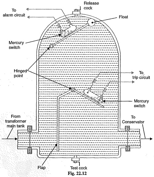
- It is a gas actuated device
- It is placed between the main tank and the conservator
- It is used in the transformer having the rating higher than 500 kVA
- It causes alarm for minor fault and tripping for a major fault
21. The key job of the relay is to
A. Increase voltage
B. Search the fault
C. Reduce resistance
D. Stop the current flow
Answer: B.
Explanation:
Search the fault
- Relay is an automatic device which detects an abnormal condition or fault in an electrical circuit
- It works on the concept of a magnetic field and Faraday law
- Relays control one electrical circuit by opening and closing contacts in another circuit
22. Which of the following is the preferred protection for ground fault?
A. Plain impedance relay
B. Directional relay
C. Reactance relay
D. Overcurrent relay
Answer: C. Reactance relay
Explanation:
Reactance Relay:
- The reactance relay is a high-speed relay.
- It consists of two elements an overcurrent element and a current-voltage directional element.
- The current element developed positive torque and a current-voltage developed directional element which opposes the current element depending on the phase angle between current and voltage.
- Reactance type relay is very suitable as a ground relay for ground fault because its reach is not affected by fault impedance.
- Also, used for the protection of short transmission lines.
Overcurrent Relay:
- Which operates only when the value of the current is greater than the relay setting time.
- Depending on the time of operation the overcurrent relay is categorized as
- Instantaneous Overcurrent relay
- Inverse time Overcurrent Relay
- Definite Time Overcurrent Relay
- Inverse Definite Time Overcurrent Relay
- Very Inverse Definite Time Overcurrent Relay
- Extremely Inverse Definite Time Overcurrent Relay
- Instantaneous Overcurrent relay
Directional Relay:
Operates when the fault is driving power to flow in a particular direction. It senses the direction of the current flowing.
Non Directional Relay:
When there is a fault in the power system, power flows through fault. Non directional relays operate irrespective of direction of flow of current.
Impedance Relay:
An impedance relay is a voltage-restrained overcurrent relay.
The relay measures impedance up to the point of fault and gives tripping command if this impedance is less than the relay setting Z.
Relay setting Z is known as replica impedance and it is proportional to the set impedance.
=2005×7.5=300A
23. A bushing, in which coaxial layers of metal foils are kept at floating potentials, is called
A. condenser bushing
B. impregnated bushing
C. graded bushing
D. non-linear bushing
Answer: A. condenser bushing
Explanation:
Bushings:
- When a high voltage conductor passes through a metal sheet or frame which is at earth potential, the necessary insulation is provided in the form of bushing.
- The primary function of the bushing is to prevent electrical breakdown between the enclosed conductor and the surrounding earthed metal work.
- The high voltage conductor passes through the bushing made of some insulating material (e.g., porcelain, steatite).
24. The diversity factor between transformers for residential lighting is:
A. 1.8
B. 2.5
C. 1.3
D. 3
Answer: C. 1.3
Explanation:
Diversity factor:
- The ratio of the sum of individual maximum demands to the maximum demand on the power station is known as a diversity factor.
- A power station supplies load to various types of consumers whose maximum demands generally do not occur at the same time. Therefore, maximum demand on the power station is always less than the sum of the individual maximum demands of the consumer. Hence diversity factor is always greater than 1.

- The knowledge of diversity factor is vital in determining the capacity of the plant equipment.
- The greater the diversity factor, the lesser is the cost of generation of power. Because greater diversity factor means lesser maximum demand. Now, lower maximum demand means a lower capacity of the plant which reduces the cost of the plant.
- Diversity factor can be used to estimate the total load required for a facility or to size the transformer.
- Diversity factors have been developed for main feeders supplying a number of feeders, and the typical values are given below.
- Residence consumer - 1.2 to 1.3
- Commercial load - 1.1 to 1.2
- Power and lighting loads - 1.50 to 2.00
25. FACTS device is used for
A. enhancing controllability
B. varying network impedance
C. increasing power transfer
D. all of the above
Answer: D. all of the above
Explanation:
Flexible AC transmission system (FACTS):
- FACTS is stand for “Flexible AC Transmission Systems” and refers to a group of resources used to overcome certain limitations in the static and dynamic transmission capacity of electrical networks.
- The IEEE defines FACTS as alternating current transmission systems incorporating power-electronics based and other static controllers to enhance control ability and power transfer ability.
Features of Flexible AC Transmission Systems (FACTS):
Shunt Controllers
A. DC series motor
B. Stepper motor
C. Synchronous motor
D. Induction motor
Answer: C. Synchronous motor
Explanation:
- FACTS devices are static power-electronic devices installed in AC transmission networks
- To increase power transfer capability.
- To increases stability, and controllability of the networks by varying network impedance through series and/or shunt compensation.
Shunt Controllers
- Shunt controllers consist of variable impedance devices like capacitors or reactors which introduce current in series with the line. The injected current is in phase with the line voltage. STATCOM, TSR, TSC, SVC.
- Series Controllers consist of capacitors or reactors which introduce voltage in series with the line. They are basically variable impedance devices. Their major task is to reduce the inductivity of the transmission line. They supply or consume variable reactive power. SSSC, TCSC, TSSC etc
- These controllers introduce current in series using the series controllers and voltage in shunt using the shunt controllers. Example UPFC.
- These controllers consist of a combination of series controllers with each controller providing series compensation and also the transfer real power along the line. Example IPFC.
26. Which of the following motors can be used for power factor correction?
A. DC series motor
B. Stepper motor
C. Synchronous motor
D. Induction motor
Answer: C. Synchronous motor
Explanation:
The power-transfer capability of EHV transmission lines can be increased by maintaining the loaded voltage within specified limits.
The following methods are used for maintaining the voltage within limits:
- Shunt capacitor bank
- Shunt reactors
- Synchronous condensers
- Static VAR compensators at heavy loads
- Series compensation
- A synchronous condenser is not a static compensation. A synchronous condenser is a synchronous motor running at no load and taking leading current.
- A synchronous condenser is an overexcited synchronous motor, which draws leading currents from the system and hence compensates for lagging vars. It is used as a reactive power compensator in some systems for power factor correction purposes.
27. Core balance current transformer (CBCT) principle is used in ______.
A. ELCB
B. MCCB
C. ACB
D. VCB
Answer: A. ELCB
Explanation:
Core Balance Current Transformer (CBCT) :
It is a ring-type current transformer through the center of which a three-core cable or three single-core cables of a three-phase system passes. This type of current transformer is normally used for earth fault protection for low and medium-voltage systems.
Diagram of CBCT :
Operating principle:
- When the system is fault-free, no current flows in the secondary of the CBCT. When there is an earth fault, the residual current (zero phase sequence current) of the system flows through the secondary of the CBCT and this operates the earth fault relay.
- Therefore, it is also called the Zero Sequence Current Transformer (ZSCT).
Explanations:
ELCB (Electric Leakage Circuit Breaker):
- ELCB is working based on earth leakage current. These devices measured the voltage on the earth conductor.
- If this voltage is not zero, this indicated a leakage current is flowing to the earth and the relay is operated. So, it is a voltage-operated earth leakage device.
- For 3 ϕ, the typical rating may be 400 V, 60 A.
MCCB (Molded Case Circuit Breakers):
- It is a protecting device that protects the circuit from overloading.
- It is mainly used in a place where adjustable tripping requires.
- The current rating of MCCB is up to 2500 amps.
ACB(Air Circuit breaker):
- It is used to provide overcurrent and short-circuit protection for electric circuits over 800 Amps to 10K Amps.
- These are usually used in low voltage applications below 450V.
VCB (Vacuum Circuit Breaker):
- It uses the vacuum as an arc extinction medium. Its rating may go up to 3 kA, 3 kV.
28. For achieving grading, the ratio between major and minor fuses shall be _______ or more.
A. 1 : 2
B. 2: 1
C. 3 : 1
D. 1 : 3
Answer: B. 2: 1
Explanation:
Explanation:
- The feeder to a DB fed from an SSB or MSB. This feeder will be protected by the HRC fuse in the SSB or MSB.
- It is necessary that the feeder protective fuse should not blow off before the motor protective fuse. This is achieved by proper grading between the fuses.
- The fuse of SSB/MSB is denoted as major fuse and that of DB is termed as minor fuse.
- For achieving grading the ratio between major and minor fuses shall be 2:1 or mor
- Feeder cable is selected by considering the 20% excess of the MD of DB. Also major fuse rating should match with the cable selection. If the cable length exceeds 75 to 100mtr, the voltage drop condition should be taken in to account.
- The voltage drop in the feeder should not be more than 3% in the maximum demand condition.
29. Isolator operates on ________ conditions.
A. Some times on load and sometimes no load
B. On load
C. No load
D. Full load
Answer: C. No load
Isolator:
- An isolator is a manually operated mechanical switch that separates a part of the electrical power.
- This separates a part of the system from the rest for safe maintenance works.
- Isolators are used to open a circuit under no load (No current condition).
- Its main purpose is to isolate one portion of the circuit from the other and is not intended to be opened while the current is flowing in the line.
- Isolators are generally used on both ends of the breaker so that repair or replacement of circuit breaker can be done without any danger.
30. In a minimum oil circuit breaker the oil is used
A. to act as circuit breaking medium only
B. for circuit breaking and providing insulation
C. for providing insulation only
D. for none of these
Answer: A. to act as circuit breaking medium only
Explanation:
Minimum Oil Circuit Breaker:

- In this type of circuit breaker, the oil is used as an arc quenching medium and it is mounted on a porcelain insulator to insulate it from the earth.
- The arc chamber of such type of circuit breaker is enclosed in bakelite paper.
- The lower portion of this breaker is supported by the porcelain and the upper porcelain enclosed by the contacts.
- In this type of circuit breaker moving contact tube moves in a vertical line to make or break contact with the upper fixed contacts mounted within the arc control devices.
- A lower ring of fixed contacts is in permanent contact with the moving arm to provide the other terminal of the phase unit.
- Within the moving contact, the tube is a fixed piston. When the moving contact moves downwards, it forces the insulating oil to enter into the arc control devices. So that the arc gets extinguished.
- Solid insulation is provided for insulation purposes.
Bulk Oil Circuit Breaker:
- In the bulk oil circuit breaker, oil is used as a dielectric or insulating medium for arc extinction.
- In oil circuit breaker the contacts of the breaker are made to separate within an insulating oil.
Advantages of oil as an arc quenching:
- The oil has high dielectric strength and provides insulation between the contacts after the arc has been extinguished
- Oil provides a small clearance between the conductors and the earth components
- The hydrogen gas is formed in the tank which has a high diffusion rate and good cooling properties