
1. A transformer transforms
A. Voltage
B. Frequency
C. Current and voltage
D. Current
Answer: C
- A transformer is an electrical device which transfers electrical energy from one circuit to another
- It works based on the principle of electromagnetic induction
- It is used for increasing or decreasing the amount of voltage or current as per our requirement based on these transformers are classified into two types step-up (increasing) or step-down (decreasing) transformer.
- A transformer can be used to either increase or decrease the voltage of a circuit.
- In other words, it can either step up (increase) or step down (decrease) the voltage.
- A transformer is necessary because sometimes the voltage requirements of different appliances are variable.
2. A transformer has negative voltage regulation, only if its load power factor is
A. Leading
B. Unity
C. Lagging
D. None of these
Answer: A
Explanation:
- Voltage regulation is the change in secondary terminal voltage from no load to full load at a specific power factor of load and the change is expressed in percentage.
- Voltage regulation for the transformer is given by the ratio of change in secondary terminal voltage from no load to full load to no load secondary voltage.
- Voltage regulation can be negative only for capacitive loads
- For leading power factor load, the secondary voltage increases slightly with an increase in the load current. Thus for leading power factor loads, the regulation is negative (raise in voltage as load current increases)
- When load is of the capacitive type, V2 > E2 & hence, regulation becomes negative.
3. In an autotransformer, the primary and secondary are ....... Coupled.
A. Magnetically coupled
B. Electrically coupled
C. Both magnetically and electrically coupled.
D. None of these
Answer: C
Answer:
- Transformer is the machine which has physical spacing and has magnetic circuit to exchange the voltage.
- They are magnetically as well as electrically coupled.
- These devices are generally used for regulation of voltage, working of induction motors etc.
- Unlike mutual transformers, autotransformers do not have separate windings.
- Due to this reason, there is no electrical isolation between the primary and secondary circuits.
- As a result, in the device, the primary is each way electrically and magnetically related to the secondary.
4. Crushed rocks are provided in the substation to
A. To avoid growing plants and weeds.
B. To provide insulation
C. To avoid fire accidents during leakage of transformer oil.
D. All of the above
Answer: D
Explanation:
- There are in fact two main reasons why gravel is laid inside substations: 1. Improved safety during earth faults and lightning strikes; and 2. Improved fire suppression during oil fires.
- We always see crushed rock spread on the surface of soil in the substation.
- The resistivity of gravel is approximately 2000 ohm – meter whereas the soil resistivity is only 100 ohm – meter.
- We say that the resistivity of gravel is 20 times than that of soil.
- The gravel acts as an insulator and back the electric field by the Ground potential rise ( GPR ).
- It provides high resistivity at the surface
- Growth of weeds not possible
- People don’t run in the switchyard therefore risk of step potential is reduced
- Reduce moisture of the soil
- Minimize the hazards caused by the movement of reptiles
A. Voltage ratio
B. Dielectric strength of the coil
C. Copper loss
D. Temperature rise
Answer: A
- One can increase the dielectric strength of oil, by changing the oil.
- Similarly, temperature rise and copper losses can also be controlled by using various techniques.
- The only thing which is constant is voltage ratio which can’t be altered.
- Voltage transformation ratio is equal to secondary induced emf to the primary induced emf.
- While the secondary and primary voltage induced are different from emfs as these are emf minus the losses in the line.
A. Decreases
B. Increases
C. Constant
D. None of these
Answer: C
Explanation:
- A transformer is designed for some constant parameters like frequency. So if the frequency increases, the secondary voltage or emf increases. But with high frequency, there is an increase in transformer losses like core loss and conductor skin effect. Also with high frequency, the magnetizing current becomes low and with low frequency the magnetizing current becomes high.
- The higher the input frequency, the higher will be the rate of change of magnetic flux, which results in higher induced EMF
- Frequency ~ Rate of Change of Magnetic Flux ~ Induced EMF
- If you are maintaining the same voltage but higher frequency, flux ( V/f ) in the transformer falls, the induced emf would hence remain the same and would not increase. Although the rate of change of flux increases due to increased frequency but the value of flux is reduced and hence the overall effect is that voltage induced in the secondary remains the same but at a higher frequency of course.
- If you are increasing primary voltage along with increasing frequency so as to maintain constant flux, only in that case the secondary voltage will increase. Therefore you can safely conclude that secondary voltage depends only upon the primary voltage and turns ratio.
A. Total loss
B. Iron loss
C. Core loss
D. Copper loss
Answer: C
Explanation:
- It is done by keeping one of the windings open (without load, usually high voltage winding is open) and applying rated voltage to other winding (usually low voltage winding because it is easier to apply rated voltage).
- The current drawn from this terminal is the no-load current corresponding to core loss component. Since the no-load current is very small it doesn’t contribute to the copper loss. Core loss is calculated by multiplying the applied voltage and no-load current.
- The core loss of the transformer
- The no-load current
- Equivalent resistance referred to the metering side.
- It is done by shorting one of the winding terminals (usually low voltage terminal) and applying a small voltage across the other winding terminals (high voltage terminal because the current in HV terminal will be less and easy to handle) and using a wattmeter to measure the power dissipated in the LV terminal. Wattmeter will indicate the full load copper loss.
- The full load copper loss
- Short circuit current
A. Infinite
B. 100 ohm
C. Zero
D. 1000 ohm
Answer: A
- In a transformer the coils are not electrically connected therefore the resistance is ideally infinite. But an autotransformer does the same using a single coil as primary with one or more taps for secondary in different parts of the coil. In this case the resistance will ideally be ZERO, or a short-circuit if you will.
- Since the primary and secondary windings are not connected to each other, one can say there exists the resistance of infinite ohms. These windings are connected to each other magnetically not electrically.
A. no reluctance
B. Low reluctance
C. High Impedance
D. Low resistance
Answer: B
Explanation:
- A transformer is a static (or stationary) piece of apparatus by means of which electric power in one circuit is transformed into electric power of the same frequency in another circuit.
- It can raise or lower the voltage in a circuit but with a corresponding decrease or increase in current.
- The physical basis of a transformer is mutual induction between two circuits linked by a common magnetic flux.
- The magnetic flux path in a transformer must have low reluctance.
- In its simplest form, it consists of two inductive coils which are electrically separated but magnetically linked through a path of low reluctance.
- The two coils possess high mutual inductance. If one coil is connected to a source of alternating voltage, an alternating flux is set up in the laminated core, most of which is linked with the other coil in which it produces mutually-induced EMF (according to Faraday’s Laws of Electromagnetic Induction e = MdI/dt). If the second coil circuit is closed, a current flows in it and so electric energy is transferred (entirely magnetically) from the first coil to the second coil.
- The first coil, in which electric energy is fed from the AC supply mains is called primary winding, and the other from which energy is drawn out is called secondary winding.
10. Which of the following part is not associated with the transformer?
A. Breather
B. Buchholz relay
C. Conservator
D. Exciter
Answer: D
Explanation:
11. If the transformer is working on, no-load is switched on to a specific source of voltage. It will draw a current
A. Same as the steady-state magnetizing current.
B. Once the steady-state magnetizing current provided to the core has huge residual flux.
C. Same as the dynamic magnetizing current.
D. Mostly, the steady-state magnetizing current relying upon the initial state of the residual flux in the transformer core.
Answer: D
Explanation:
- Whenever a transformer is on no-load, the secondary winding has no load connected to it.
- The transformer must actually withdraw zero current from the primary side.
- But practically even on no-load, a small amount of current is drawn from the primary side, to set up the required magnetic flux in the magnetic core.
- At no load, the transformer draws some current (Im) in order to establish the flux in the transformer core which lags the applied voltage by 90° ( since flux is required to create a magnetic pool in order to transfer energy from one port to another) called as magnetizing current.
- It is several times the steady-state magnetizing current, depending upon the initial state of the residual flux in the transformer core.
- This magnetizing current (no-load current) is about 3-5% of the full load current and it accounts for the losses in a transformer.
12. During short circuit test of the power Input to a transformer comprises predominately.
A. Eddy current loss
B. Hysteresis loss
C. Copper loss
D. Iron loss
Answer: C
Explanation:
- Copper losses in a transformer at full load
- Series branch parameters in ohmic values
- % resistance, % reactance and % impedance of the transformer
- We need to increase the applied voltage towards rated voltage up to rated current passes through the short-circuited secondary winding. It is conducted on the HV side of the transformer
- Since the applied voltage is small, the flux is also small. Therefore, core losses are small hence core loss can be neglected. Therefore, the wattmeter reading can be taken as equal to copper losses in the transformer.
- So, input power supplied during a short-circuit test on a transformer equals to copper losses.
13. Buck-boost transformers are used when
A. The supply voltage matches the voltage required by the load.
B. The supply current matches the voltage required by the load.
C. The supply voltage does not match the voltage required by the load.
D. The supply current does not match the voltage required by the load.
Answer: C
Explanation:
- A buck–boost transformer is a type of transformer used to make adjustments to the voltage applied to alternating current equipment. Buck–boost connections are used in several places such as uninterruptible power supply (UPS) units for computers and in the tanning bed industry.
- A buck-boost transformer is a type of transformer which is primarily used to adjust the voltage level applied to various electric equipment. Buck-boost transformers are utilized in in several applications such as uninterruptible power supplies (UPS) units for computers.
14. The transformer draws the current when its secondary winding is open.
A. Full load primary current
B. Full load secondary current
C. No-load primary current
D. No-load secondary current
Answer: C
Explanation:
- The secondary side of a current transformer should never be kept in open condition because, when kept open, there is a very high voltage found across the secondary side.
- This high voltage causes a high magnetizing current to build up on the secondary side which in turn causes high flux and makes the core to saturate.
- When the secondary winding of a current transformer is open-circuited with the primary winding energized, the large voltage may act as safety hazard for the operators and many even rupture the insulation.
- The secondary winding of the current transformer is always kept closed because if it open-circuited, the current transformer would develop an extremely high voltage across the secondary terminals.
- It may lead to damage to the transformer insulation as well as arcing across the terminal.
15. The purpose of providing an iron core in a transformer is to
A. provide support to windings
B. reduce hysteresis loss
C. decrease the reluctance of the magnetic path
D. reduce eddy current losses
Answer: C
Explanation:
- The core of the transformer is made up of soft iron it has high coercivity and low retentivity.
- The primary coil and the secondary coil are wound on the soft iron core.
- The iron core decreases the reluctance of the magnetic path to flow magnetic flux.
- The soft iron core has high permeability and it provides a complete linkage of the magnetic flux of the primary coil with the secondary coil.
- In transformers, the two coils are wound onto the same iron core. The purpose of the iron core is to channel the magnetic flux generated by the current flowing around the primary coil so that as much of it as possible also links the secondary coil. The iron core is also used to decrease the magnitude of magnetizing current.
- Magnetic circuit (consisting of core, limbs, yoke, and damping structure)
- Electrical circuit (consisting of primary and secondary windings)
- Dielectric circuit (consisting of insulations in different forms and used at different places)
- Tanks and accessories (conservator, breather, bushings, cooling tubes, etc.)
- The purpose of the iron core is to channel the magnetic flux generated in the primary coil.
- The main problem with the transformer core is its hysteresis and eddy current losses.
- Hysteresis loss in the transformer mainly depends upon its core materials.
- A small quantity of Silicon alloyed with low carbon content steel produces material for the transformer core.
- It has low hysteresis loss and high permeability.
A. output voltage fluctuation from no load to full load is the least.
B. output voltage fluctuation with power factor is least.
C. difference between primary and secondary voltage is the least.
D. difference between primary and secondary voltage is maximum.
Answer: A
Explanation:
- Good voltage regulation means minimum regulation i.e. less fluctuation in full load voltage compared to no-load voltage.
- Efficiency: Efficiency (η) of a transformer is the ratio of output to input. The transformer with fewer losses gives high efficiency. So, the transformer with higher efficiency is desired.
- Voltage Regulation can be defined as the drop in receiving end voltage from no load to full load expressed as a percentage of the full load receiving end voltage.
- For a transmission line, it is expected that the receiving end and sending end voltage are the same.
- Therefore, a better voltage regulation means a less voltage drop and hence a lower value of voltage regulation.
- The ideal voltage regulation should be zero.
- Zero voltage regulation indicates that there is no difference between its no-load and its full-load voltage.
- This is not practically possible and is only valid theoretically for ideal devices.
- Therefore, for the practical application, it should be as low as possible for the proper operation of the electrical devices.
17. If the percentage impedances of the two transformers working in parallel are different, then
A. Transformers will be overheated
B. Power factors of both the transformers will be same
C. Parallel operation will be not possible
D. Parallel operation will still be possible, but the power factors at which the two transformers operate will be different from the power factor of the common load
Answer: D
Explanation:
- Same voltage ratio or same turn ratio.
- Same phase angle shift.
- Same frequency rating of both the transformer.
- The same polarity of the transformers.
- Both should be connected in the same phase sequence.
- Mostly this parameter is used to enhance plant power capacity by connecting existing transformers in parallel that have the same kVA rating, but with different percent impedances.
- This is common when budget constraints limit the purchase of a new transformer with the same parameters. It is important to understand that the current divides in inverse proportions to the impedances and a larger current flows through the smaller impedance.
- Thus, the lower percent impedance transformer can be overloaded when subjected to heavy loading while the other higher percent impedance transformer will be lightly loaded.
- Thus, the power factors at which the two transformers operate will be different from the power factor of the common load.
18. An ideal transformer will have maximum efficiency at a load such that
A. copper loss = iron loss
B. copper loss < iron loss
C. copper loss > iron loss
D. none of the above
Answer: A
Explanation:
19. A Buchholz relay can be installed on
A. autotransformers
B. air-cooled transformers
C. welding transformers
D. oil cooled transformers
Answer: D
- Buchholz relay is a protection device which is normally used in large oil absorbed transformers; It is a kind of oil and gas actuated relay.
- Whenever a small fault happens within the electrical device, heat is generated by the fault currents
- The generated heat causes decomposition of electrical device oil and gas bubbles are generated
- These gas bubbles run in the upward direction and obtain collected within the Buchholz relay
- The collected gas relocates the oil in Buchholz relay and therefore the displacement is similar to the amount of gas collected
- The dislocation of oil causes the higher float to shut the higher mercury switch to connect an alarm circuit
- Hence, once a small fault happens, then the alarm will be activated; The collected quantity of gas specifies the level of fault occurred
- Different types of faults have different types of oil flow and thus a fault can be recognised easily, and proper action can be taken.
20. The full-load copper loss of a transformer is 1600 W. At half-load, the copper loss will be
A.6400 W
B.1600 W
C.800 W
D.400 W
Answer: D
Explanation:
Copper Loss = I^2R
where I is the current flowing through the transformer and R is the resistance of the copper windings.
Since copper loss is proportional to the square of the current, it can be assumed that at half-load, the current flowing through the transformer will be half of the full-load current. Therefore, the copper loss at half-load can be calculated as follows:
Copper Loss at Half-Load = (1/2)^2 x Full-Load Copper Loss
Copper Loss at Half-Load = (1/4) x 1600 W
Copper Loss at Half-Load = 400 W
Therefore, the correct answer is option D, i.e., 400 W.
21. The size of a transformer core will depend on
A. frequency
B. area of the core
C. flux density of the core material
D. (A) and (B) both
Answer: D
Explanation:
- The size of the transformer will depend on the frequency and area of the core.
- The area of the window and cross sectional area of the limb are the main dimensions of a transformer, the product of which is directly proportional to the size and weight of the transformer. More the product (area), bigger and heavier is the transformer.
- For a given transformer rating, as the frequency increases the product of window area and cross sectional area of the limb decreases; which means the iron required for the core decreases. Therefore as the frequency increases, the transformer becomes lighter and smaller in size.
B. A D.C. circuit has more losses
C. Faraday's laws of electromagnetic induction are not valid since the rate of change of flux is zero
D. None of the above
Answer: C
- The transformer works on the principle of mutual induction, for which current in one coil must change uniformly
- If dc supply is given, the current will not change due to constant supply and transformer will not work
- Faraday's laws of electromagnetic induction are not valid since the rate of change of flux is zero
- Practically winding resistance is very small
- For dc, the inductive reactance is zero as dc has no frequency
- So total impedance of winding is very low for dc
- Thus, winding will draw very high current if dc supply is given to it
- This may cause the burning of windings due to extra heat generated and may cause permanent damage to the transformer
23. Which of the following loss in a transformer is zero even at full load ?
A.Core loss
B.Friction loss
C.Eddy current loss
D.Hysteresis loss
Answer: B
- Friction losses are involved with rotating parts of a machine. Since in a transformer all parts are stationary, friction losses will always be equal to zero, irrespective of the loading condition.
- A transformer is a static device i.e. transformer does not consist of any type of moving component, due to which there is no frictional loss in the transformer.
- Hence the efficiency of the transformer is highest among the all other electrical devices. It is generally more than 90%.
- The transformer works on the principle of Faraday’s Electromagnetic Induction.
- The sum of eddy current loss & hysteresis loss is known as iron loss or core loss, which are occurred in the core of the transformer.
- An open circuit test is performed to calculate the iron or core losses of the transformer.
- A short circuit test is used to find a copper loss in the transformer.
A. iron core
B. copper winding
C. winding insulation
D. frame or case
Answer: C
Explanation:
- 1. Overloading: When a transformer is overloaded, the copper winding generates more heat than it can dissipate, leading to overheating of the winding insulation.
- 2. Poor ventilation: If the transformer is not properly ventilated, the heat generated by the copper winding cannot be dissipated effectively, leading to overheating of the winding insulation.
- 3. Faulty insulation: If the winding insulation is faulty or damaged, it can lead to overheating of the copper winding, which in turn can cause further damage to the insulation.
A. 0.2 to 0.5 percent
B. 2 to 5 percent
C. 12 to 15 percent
D. 20 to 30 percent
Answer: B
Concept:
Operation of transformer on no load:
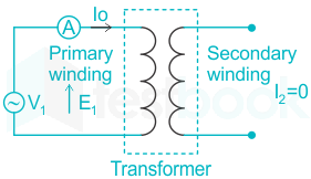
When the transformer is operating at no load, the secondary winding is open-circuited, which means there is no load on the secondary side of the transformer and, therefore, current in the secondary will be zero.
While primary winding carries a small current I0 called no-load current which is 2 to 10% of the rated current.
The no-load current consists of two components:
Reactive or magnetizing component (Im):
It is in quadrature with the applied voltage V1. It produces flux in the core and does not consume any power.
Active or power component (Iw): It is also known as a working component. It is in phase with the applied voltage V1. It supplies the iron losses and a small amount of primary copper loss.
Phasor diagram:
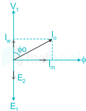
- The function of the magnetizing component is to produce the magnetizing flux, and thus, it will be in phase with the flux.
- Induced emf in the primary and the secondary winding lags the flux ϕ by 90 degrees.
- The primary copper loss is neglected, and secondary current losses are zero as I2 is zero.
- Therefore, the current I0 lags behind the voltage vector V1 by an angle ϕ0 called the no-load power factor angle and is shown in the phasor diagram.
- The applied voltage V1 is drawn equal and opposite to the induced emf E1 because the difference between them is negligible at no load.
- Active component Iw is drawn in phase with the applied voltage V1.
- The phasor sum of magnetizing current Im and the working current Iw gives the no-load current I0.
Conclusion:
The no-load current drawn by a transformer is usually 2 to 5 percent of the full-load current.
26. The chemical used in breather for transformer should have the quality of
A. ionizing air
B. absorbing moisture
C. cleansing the transformer oil
D. cooling the transformer oil
Answer: B
- When the transformer is loaded, the temperature of the transformer insulating oil increases, consequently the volume of the oil is increased.
- As the volume of the oil is increased, the air above the oil level in the conservator will come out.
- When the transformer is less load or no load, the temperature of the transformer insulating oil decreases, consequently the volume of the oil is decreased, which again causes air to enter into conservator tank.
- The natural air always consists of more or less moisture in it and this moisture can be mixed up with oil if it is allowed to enter into the transformer.
- The air moisture should be resisted during entering of the air into the transformer to overcome insulation failure or short circuit inside the transformer
- A silica gel breather is the most commonly used way of filtering air from moisture.
- Silica gel breather for transformer is connected with conservator tank by means of breathing pipe.
- Silica gel crystal has the property of absorbing moisture.
- When air passes through these crystals in the breather; the moisture of the air is absorbed by them, therefore, the air reaches the conservatory becomes quite dry.
- The oil in the oil sealing cup acts as a barrier between silica gel crystal and air when there is no flow of air through the silica gel breather.
- The color of silica gel crystal is dark blue but when it absorbs moisture it becomes pink.
A. to project against internal fault
B. to reduce copper as well as core losses
C. to cool the transformer oil
D. to take care of the expansion and contraction of transformer oil due to variation of temperature of the surroundings.
Answer: D
Explanation:
- Transformer oil is used for the purpose of insulation and cooling.
- The oil should not be allowed to come in contact with atmospheric air, as it may spoil its insulating properties.
- To prevent this, we use conservators.
- The conservator consists of an airtight metal drum fixed above the level of the top of the oil tank and connected with it by a pipe.
- The function of a conservator is to take up contraction and expansion of oil without allowing it to come in contact with outside air.
28. A transformer can have regulation closer to zero
A. on full load
B. on overload
C. on leading power factor
D. on zero power factor
Answer: C
Explanation:
- Voltage regulation is the change in secondary terminal voltage from no load to full load at a specific power factor of load and the change is expressed in percentage.
- Voltage regulation for the transformer is given by the ratio of change in secondary terminal voltage from no load to full load to no load secondary voltage.
- In a transformer, minimum voltage regulation occurs when the power factor of the load is leading.
- The voltage regulation of the transformer is zero at a leading power factor load such as a capacitive load.
- This is the leading power factor at which voltage regulation becomes zero while supplying the load.
29. Power transformers are designed to have maximum efficiency at
A. nearly full load
B. 70% full load
C. 50% full load
D. no load
Answer: A
- Power transformers have maximum efficiency at full load. Power transformers are intended to be as efficient as possible under full load since they are used at full load. The transformer's output power is 0 when the load is not connected across the transformer's secondary. Power transformers step up or down the applied input power (Voltage). The efficiency of the power transformer is always greater than 90%. So it is considered a highly efficient electrical device.
- From many experiments, power transformers perform with maximum efficiency at full load. When the load increases, then the output of the power transformer also increases. When the bag is null, the output power will be zero.
- Power transformer efficiency is the ratio of output power to input power.
- When the load is low, the power transformer experiences hysteresis and eddy current loss. So the efficiency of the power transformer became less.
- When the load of the transformer increases, then the efficiency increases. Both are directly proportional to each other.
- When the load of the power transformer is zero, then the output voltage is zero, and efficiency also becomes zero.
- The efficiency of transformer= V1/V2=P1/P2=I2/I1
30. Hysteresis loss in a transformer varies as (Bmax = maximum flux density)
A. Bmax
B. Bmax1.6
C. Bmax1.83
D. B max2.4
Answer: B
- These are due to the reversal of magnetization in the transformer core whenever it is subjected to the alternating nature of magnetizing force.
- Hence, Hysteresis loss depends on the volume of material, class of material, frequency & flux density.
- When the Materials subjected to rapid reversals of magnetism then it is having a narrow hysteresis loop hence it should have higher permeability and low hysteresis loss and vice versa.
- Hysteresis loss in a magnetic material depends upon the area of the hysteresis loop, frequency of reversed field, and volume of magnetic material.
- Eddy current loss in the transformer is I2R loss present in the core due to the production of eddy current.
- At a constant (V/f) ratio, eddy current losses are directly proportional to the square of the frequency.
- Hysteresis loss in a transformer varies as (Bmax = maximum flux density) Bmax1.6.